Previously, we showed how to control a SPIKE3 robot with a game pad. It is simple and fun. But wouldn’t it be nice to also be able to drive your custom RGB NeoPixels LEDs at the same time? For example, to build a remote-controlled vehicle with custom lights. Here’s an advanced tutorial that explains how to add RGB LEDs to your SPIKE hub with LMS-ESP32.
Emulating Lego Sensors
The way we achieve communication between our LMS-ESP32 board and the SPIKE3 hub, is by emulating an original Lego Sensor. Lego sensors use the so-called LPF-2 protocol. The team at Pybricks created an insightful LPF-2 technical description.
In our article about block coding the gamepad, we used a simple Color Sensor. In this article, we emulate a 3×3 Color Matrix. Using SPIKE Word Blocks, you use the SPIKE Essential 3×3 Color Matrix Word Block to drive your custom 3×3 Color Matrix or any other 9-NeoPixel application.
If you want both pixels and gamepad, SPIKE Python is the only option, however. Read on to learn how to do both!
Step 1: Install BluePad32 for Spike3 Firmware on the LMS-ESP32
To install the new BluePad32 Spike3 firmware to your LMS-ESP32 board, head over to https://firmware.antonsmindstorms.com/ and choose the correct firmware type. Connect your LMS-ESP32 board to the PC and follow the steps during the firmware flashing process.
Step 2: Connect RGB LEDs (NeoPixels)
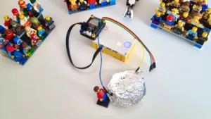
For the first test, we will attach several NeoPixels to port GPIO 21 of the LMS-ESP32 board. Currently, the SPIKE Essentials matrix sells for almost €50, so we created our Color Matrix from a few LEGO Sized RGB LEDs. It is much cheaper, and it can show any color instead of just the 10 colors of the LEGO Matrix.
Step 3: Create Word Block program
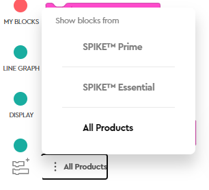
To use Word Blocks, you can use the Spike Essential 3×3 Matrix word block. You will see these blocks in the Light section when you select All Products in the lower left of the SPIKE Word Blocks screen.
By default, the Lego Matrix pixels are mapped to the first 9 NeoPixels, attached to GPIO 21 of your LMS-ESP32 board.
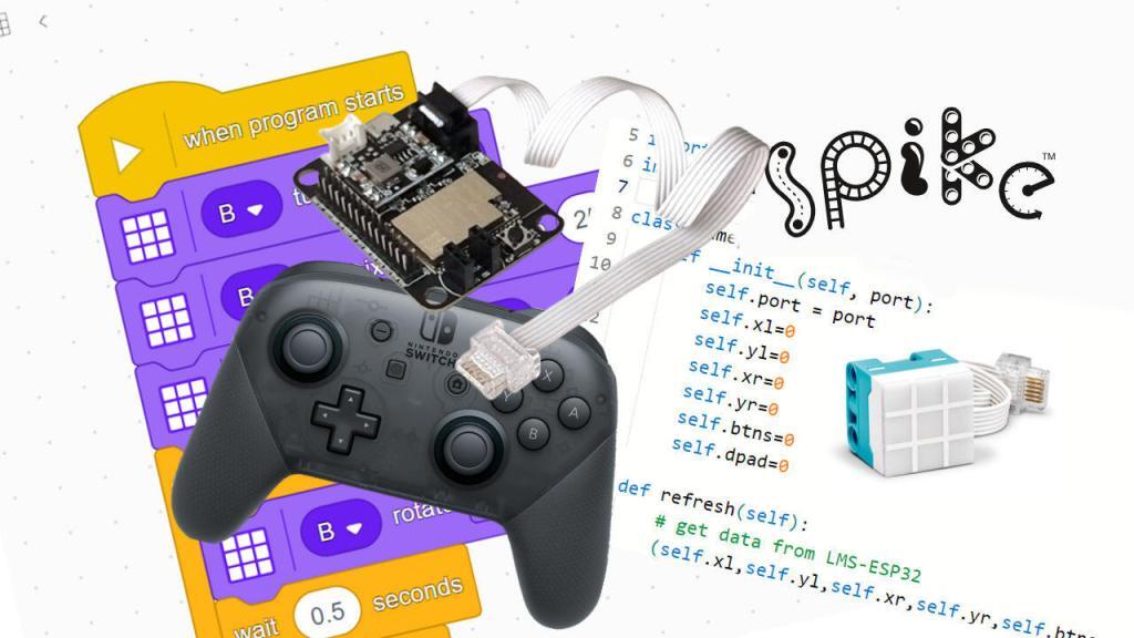
Step 4: Expand your program with a gamepad using Python
In the Python environment, you can use the color_matrix functions. See the LEGO documentation for this.
Connect a gamepad to your board. Depending on the type of Gamepad, the pairing might be different. On my Nintendo Pro controller, I press the small pairing button for a few seconds. When the green indication light is fixed to the first position, the gamepad is paired.
Here is a short test program to see whether the gamepad communication over Bluetooth is working. It will just print the gamepad controller state. Copy the code below and paste it into a new Python SPIKE Prime project.
from hub import port
import time
import color
import color_matrix
import device

class Gamepad:
    def __init__(self, port):
        self.port = port
        self.lx=0
        self.ly=0
        self.rx=0
        self.ry=0
        self.buttons=0
        self.dpad=0

    @staticmethod
    def scale100(pos):
        # Scale the values to integers of -100,100 and add deadzone
        if -10 < pos < 10: # deadzone
            return 0
        else:
            return int((pos*100)/127)

    def refresh(self):
        # get data from LMS-ESP32
        (self.lx,self.ly,self.rx,self.ry,self.buttons,self.dpad,_,_)=device.data(self.port)
        # optional scale and deadzone
        self.lx = self.scale100(self.lx)
        self.ly = self.scale100(self.ly)
        self.rx = self.scale100(self.rx)
        self.ry = self.scale100(self.ry)

gp=Gamepad(port.B)

while (1):
    gp.refresh()
    print(gp.lx,gp.ly,gp.rx,gp.ry,gp.buttons,gp.dpad)
    time.sleep_ms(200)
The Gamepad class is just a wrapper around the device.data function. This function replies with a tuple of 8 values. The first 6 values are populated with lx, ly, rx, rz, buttons, dpad. The values for all coordinates of the joysticks are between 0 and 255.
Step 5. Customize the LEDs with the web configurator
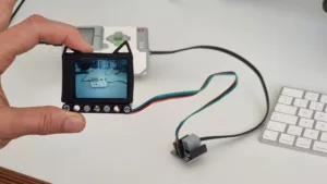
At bluepad.antonsmindstorms.com, we have a web configuration tool to configure how the LMS-ESP32 board emulates SPIKE Sensors. You can use the configurator while the board is connected to the SPIKE hub, for quick prototyping.
When the LMS-ESP32 is connected, the configurator will show the onboard settings. The configuration is stored in the non-volatile memory of the LMS-ESP32 with the Send & save button.
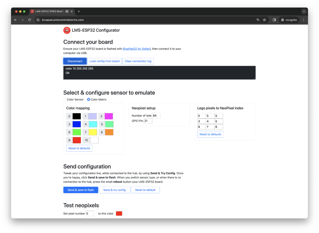
By default, we assume that the NeoPixels are connected to GPIO21. With the configurator, you can choose another pin and another number of LEDs. After sending the configuration, you can quickly test the NeoPixels by entering a NeoPixel pixel index and selecting a color at the bottom of the configurator.
Mapping Lego Colors to NeoPixel colors
The Lego 3×3 Color Matrix uses a palette of 10 different colors. The colors are predefined in this sensor and cannot be changed. For our NeoPixels, however, we can select every RGB combination we like. To use our color palette, we need to map NeoPixel RGB color to the palette color index. In the Web Configurator, we can select any RGB color with a color picker.
Mapping Lego 3×3 Matrix pixels to NeoPixels
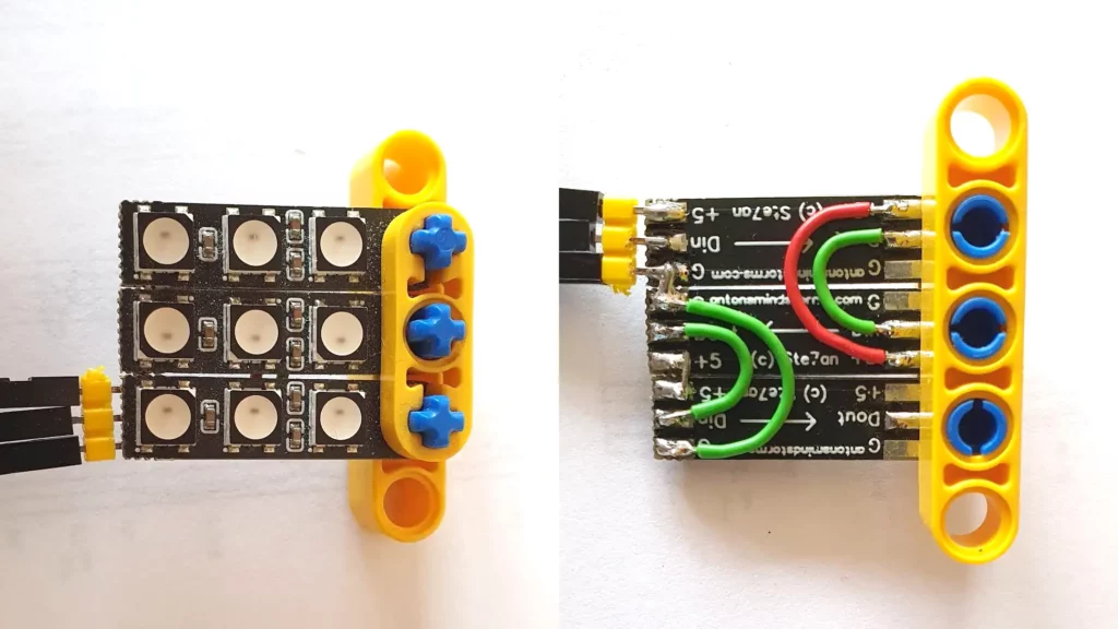
In the 3×3 Color Matrix, you address individual pixels by their column and row index, where (1,1) is the top left and (3,3) is the bottom right pixel. If you use custom RGB NeoPixels, they likely don’t come in a 3×3 grid, but in various shapes (circles, larger matrices, strips, etc.) and you want to be flexible on how to map the Lego pixels to your NeoPixels. We use a linear index, as indicated in the picture below:
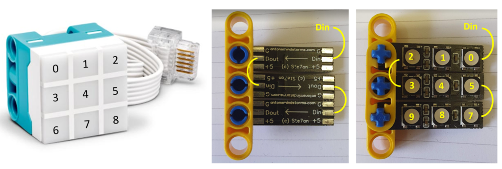
Next to the original Lego Color Sensor, you see a 3×3 matrix built from our LED Strips. The matrix consists of 3 strips connected with Dout to the Din of the next strip. The NeoPixel numbering of LEDs corresponds to the numbers on the right-hand side picture. If we used the Lego LED numbering, the LEDs would be represented in reverse. Therefore, we need to map the Lego numbering to the NeoPixel LED numbering in the Web Configurator. This is done by filling out the mapping form as shown below.
Remember that you can quickly test the NeoPixels LED positions by using the NeoPixel Pixel and Color feature in the upper part of the Web Configurator.
Next post: A gamepad and pixel demo
In our next blog, we will combine RGB pixels and gamepad with a hot rod car. Stay tuned!
Background information
Internal working of Bluepad LMS-ESP32 gamepad firmware
A typical Lego LPF-2 sensor has different modes of operation. For example, the Lego Color Sensor can measure reflected light, can detect colors, or can measure the color components. For these different functions, so-called modes are configured in the firmware of the sensor. Each mode has different capabilities in terms of the type and number of data elements that can be exchanged. In the case of the Lego 3×3 Color Matrix, four different modes are implemented in the firmware. Only a single mode seems to be used. As a Color Matrix is a device that only receives data from the Lego SPIKE Hub, all these modes only support traffic flowing from the hub to the LPF-2 sensor.
We used a logic analyzer to sniff the data transmitted on the wires between the SPIKE hub and the 3×3 hub. We were astonished to find out, that the Color Matrix is sending a continuous stream of data which is a replication of the received data.
This brought up the idea to send different data to the hub, instead of replicating the received packets. Using the device.data function, we could see that we had a single byte of the 8-byte response under our control. Although mode 2 is used for sending the colors to the Color Matrix, it turned out that when we increased the number of data elements of Mode 0 (which was 1) to 8, we had at least 6 bytes under our control. And that is enough for sending gamepad data to the hub. Namely, 2 bytes for the left joystick’s x- and y-coordinates, 2 bytes for the right joystick, a single byte for the buttons, and the last byte for the directional pad buttons that are pressed.
If you are interested, take a look at the internals of the firmware in our GitHub repo.
Serial command line
The Web Configurator works by using the Web Serial API and communicates directly to the serial port (over USB) of the LMS-ESP32. We have implemented a simple command line interface with the following commands:
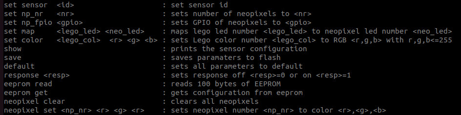
These commands can also directly be executed from any serial terminal (e.g., Google online serial terminal). The NeoPixel commands to clear and to set a specific pixel can be handy to figure out which pixel is on which NeoPixel index.
Conclusion
We already supported the old SPIKE Prime 2, MINDSTORMS Robot Inventor and Pybricks for using with our LMS-ESP32 module. As of now, we also support programming in the SPIKE 3 app. We are curious to find out what kind of application you come up with using this LMS-ESP32 board together with your SPIKE3 robot. Please let us know in the comments below. All example programs are on our GitHub repo.