In this article, you’ll learn how to connect a Bluetooth gamepad to the SPIKE Prime or Robot Inventor hub without lag but with Word Blocks/Scratch. We use an extra piece of hardware, the LMS-ESP32, to convert the Bluetooth signals to a LEGO LPF2 sensor format.
Bluetooth Gamepad as a LEGO sensor in Word Blocks
In a previous post, we showed how to connect a PS4 or Nintendo gamepad to the new LEGO Robot Inventor or SPIKE Prime hubs using Python on the LEGO hub. That post gives some background on the different types of Bluetooth supported by LEGO hubs.
In this how-to guide, we use the LMS-ESP32 board flashed with a new firmware that presents the LMS-ESP32 board as a standard sensor. We ‘fool’ the Large Hub into thinking it is a LEGO Distance sensor. The name of this specific firmware is Bluepad32. It is open-source and Arduino-based.
Next, we created several MyBlocks to read the two analog joysticks, the D-Pad, and all the buttons on a gamepad. And there is more! We have experimental support for driving NeoPixel LEDs and Servo motors connected to the LMS-ESP32 from the Word Block environment. Read about this near the end of this blog.
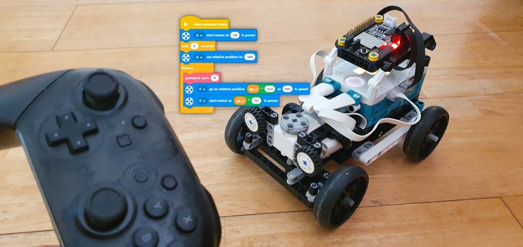
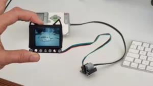
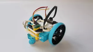
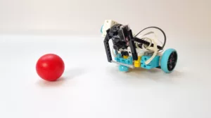
Hot Rod controlled by lag-less Bluetooth Gamepad in Word Blocks
The video below shows the Hot Rod model controlled by a Nintendo Gamepad. A PS4 gamepad works too. The program runs on the LEGO hub and is written in Word Blocks.
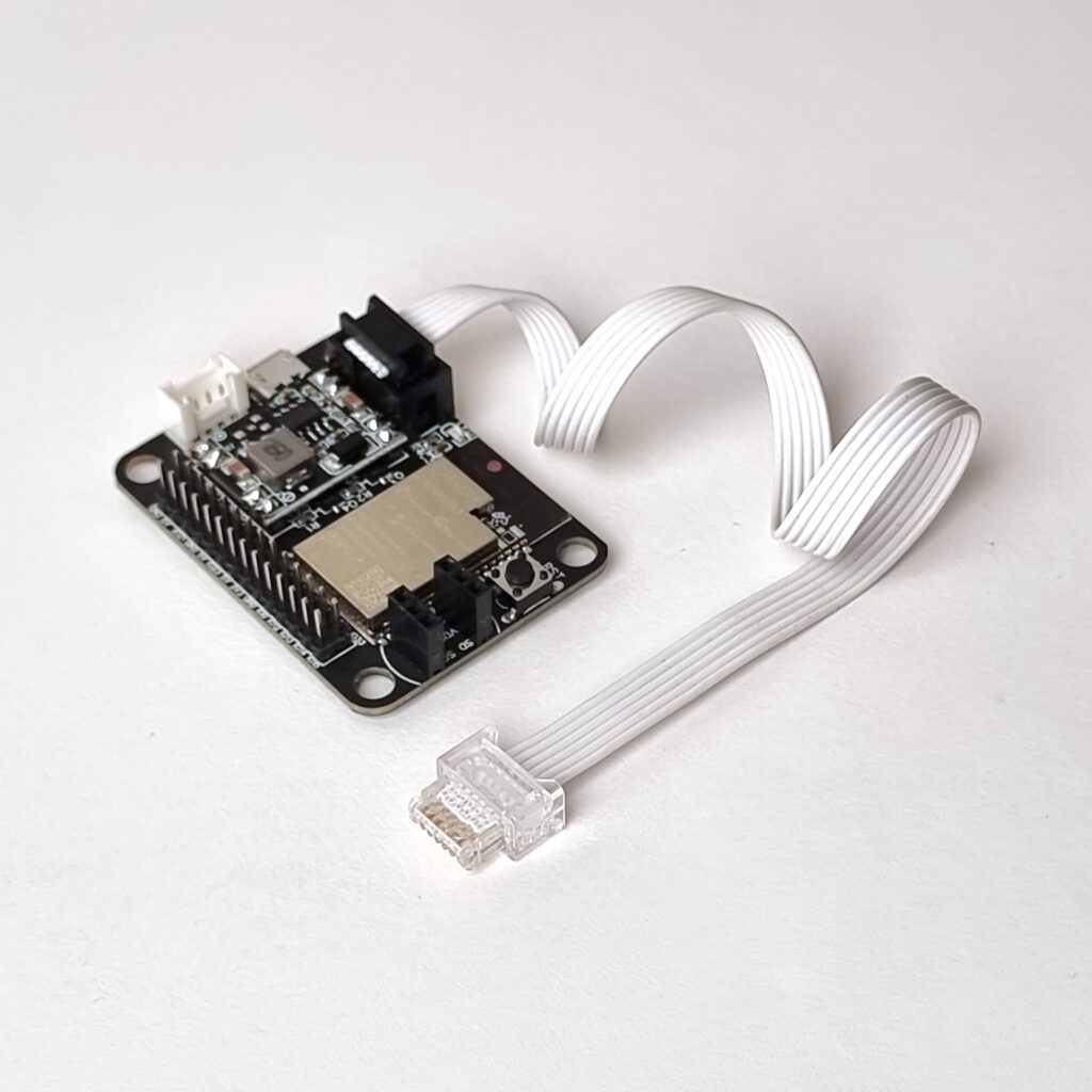
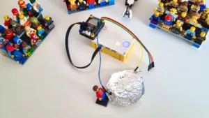
LMS-ESP32 board for SPIKE and MINDSTORMS (LMS-ESP32-v1.0)
This all-new MicroPython expansion board for LEGO MINDSTORMS Robot Inventor, Spike Prime, and EV3. You can easily connect this LMS-ESP32-v1.0 board to your LEGO robot and use it as an interface to a limitless range of third-party electronics. You can now connect any protocol to your LEGO Robot: I2C, UART, SPI, WS2812, Neopixel, I2S, WiFi, Bluetooth Classic, BLE, Bluetooth HID, Hobby Servo PWM, …
Step-by-step guide for programming Gamepad direct link in LEGO Word Blocks
This guide explains how to set up a lag-less direct gamepad connection to the LEGO Robot Inventor or SPIKE Prime hub, programmed with Scratch / Word Blocks.
- Build the Hot Rod or any other contraption that you want to remotely control
We build the Hot Rod model in this example.
- Flash your LMS-ESP32 board with the BluePad32-LMS firmware
Head over to the Web-based LMS-ESP32 installer. Connect the USB port of your LMS-ESP32 to your PC, select “BluePad32 for LMS word blocks projects” and select ‘CONNECT’. You can flash the Micropython firmware back at any time using the same web-based esp32 flash tool.
- Connect the LMS-ESP32 board to the LEGO hub
In this example, we assume that you connect the LMS-ESP32 to Port D of the LEGO hub
- Obtain the LMS words block program
Download the Hot Rod Word Block Program and open the program in the MINDSTORMS Robot Inventor app.
The main program looks like this: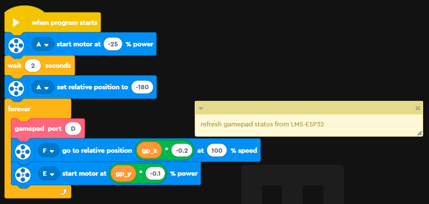
The forever loop calls thegamepadMyBlock with the LMS-ESP32 port as a parameter. This MyBlock refreshes the two variablesgp_xandgp_ywith the values of the analog joystick of the gamepad. These values range from -512 to 512.
In this program, below the main loop, you will find the definitions of the various MyBlocks that we defined for getting the GamePad to work. - Connect the GamePad to the LMS-ESP32
Depending on the type of GamePad you use, you will have to connect the gamepad by pressing a pairing button. Once you have connected the gamepad, a distance sensor will show up that is connected to port D. The preview of the MINDSTORMS app shows only positive values of the x-direction. By moving the analog joystick to the right, you should see the ‘distance’ increase.
- Run the program
You can run the program now and control the vehicle with the analog joystick of the gamepad.
How the Bluetooth gamepad Word Blocks template works
The MINDSTORMS word block environment does not allow for low-level reading of a LEGO Sensor. We provide a BluePad32 Word Blocks template that implements all the MyBlocks needed for working with the BluePad32 firmware. The template contains a simple test main loop. You can replace the loop with your own main loop. In MINDSTORMS Word blocks you can not copy MyBlocks from one program to the other, consequently, we use a template program from which you can start your own implementation.
Gamepad MyBlock
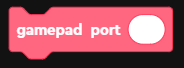
The gamepad MyBlock reads the gamepad status in the global variables gp_x, gp_y, gp_rx, gp_ry, gp_buttons and gp_dpad. When the port-parameter is left empty, the default port will be Port A. Otherwise, use a single character A-F to configure the port to which the LMS-ESP32 is connected.
The table below shows the definition of the global gamepad-related variable.
| Variable | Mode, word | Description |
|---|---|---|
gp_x | M0, word 0 | Gamepad left axis X |
gp_y | M0, word 1 | Gamepad left axis Y |
gp_rx | M0, word 2 | Gamepad right axis x |
gp_ry | M0, word 3 | Gamepad right axis y |
buttons | M0, word 4 | Button status A=2, B=1, X=8, Y=4, left shoulder=16, right shoulder=32, left trigger=64, right trigger=128 analogue left stick= 256, analog right stick=512 |
dpad | M0, word 5 | Dpad status up=1, down=2, right=4, left=8 |
When multiple keys are pressed simultaneously, the value read from the button or dpad variables is the sum of the corresponding values of the buttons pressed. Since there is no Bitwise or operator in Word Blocks, we added a MyBlock to check for a specific key pressed.
NeoPixels and Servo motor MyBlocks (experimental)
Up to 4 servo motors can be connected to the LMS-ESP32 on GPIO ports 21,22,23 and 25. A NeoPixel array can be connected to the default GPIO pin 12.
The servo motors and NeoPixels can be controlled by the above MyBlocks. Below we describe each of the MyBlocks.
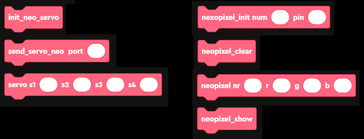
init_neo_servo
This MyBlock needs to be called once at the start of your program, only if you are using servo’s and/or neopixels. The MyBlock initializes the byte arrays and global variables needed for communicating with the LMS-ESP32.
send_servo_neo(port)
Every time a change needs to be communicated to the LMS-ESP32 with regards to servo’s or neopixels, this function needs to be called. When the port parameter is left empty, the default port will be Port A. Multiple changes to the neopixels can be accumulated before calling this function.
servo(s1,s2,s3,s4)
This MyBlock sets the values (0-180) for the servo’s S1, S2, S3, and S4 which are connected to GPIO21, 22, 23, and 25, respectively. After calling this MyBlock, the send_servo_neo(port) MyBlock needs to be called.
neopixel_init(num,pin)
Initializes num NeoPixels connected to GPIO Pin pin. By default, an array of 64 neopixels is defined at GPIO12.
neopixel_clear
This MyBlock sets all NeoPixels to the value (0,0,0), effectively switching them off. To effectuate this command, it should be followed by a call to send_servo_neo(port).
neopixel(nr,r,g,b)
This MyBlock sets the values for NeoPixel number nr to r,g,b. Only after calling the send_servo_neo(port) MyBlock, the new values are passed to the LMS-ESP32. Multiple neopixels can be set before calling send_servo_neo(port) function. To show the newly set NeoPixels, the function neopixel_show should be called, again followed by a call to send_servo_neo(port).
neopixel_show
This MyBlock lets the LMS-ESP32 show the new values of the NeoPixels. A call to this MyBlock should be followed by a call to send_servo_neo(port).
Debug MyBlocks
In the MINDSTORMS robot inventor app, a special debug mode can be enabled. This also gives access to 4 so-called Debug Blocks. You can read how to enable debug mode on the GitHub page of Maarten Pennings.
We use the following 3 debug Blocks:
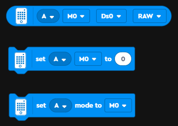
The first Blocks reads the n-th raw value of the sensor from the specified mode. Each sensor can have multiple modes. In the BluePad32-LMS firmware, we emulate a single sensor in a single mode.
The second Block allows sensing data – this can be an array of values – to the specified mode M0 of the sensor.
The third Block switches between modes of a sensor. This needs to be called prior to reading or sending values from another mode than the last one used.
Implementation of gamepad MyBlock using debug Blocks
Using the Debug Blocks for reading raw values of a sensor we fill global variables according to the status of the GamePad. Below the MyBlock definition is shown.
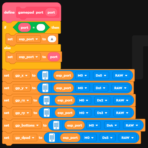
Each of the global variables is filled with the value read from mode M0 of the sensor with a mapping of the specific word to the variable as shown in the table above.

Hi Anton,
good work, I have purchased the LMS for my son… now I need some help. I don’t find the bitwise block for check the button pressed.
Bye
What tutorial are you following?
Which version of the Word Block app are you using? The SPIKE Prime version 2 (now called legacy) or the new version 3, or the Mindstorms Robot inventor app?
Hi, tnx for the fast reply!
I use the latest BluePad32 Word Blocks template from GitHub with the Lego Mindstorms Robot Invertor App
Hi Anton,
Is the source code for the “BluePad32 for word blocks” firmware available somewhere?
I want to recompile it with a newer version of BluePad32 because the current version doesn’t support PS3 controllers.
Thanks in advance
Hi Sandor,
sure, the source code can be found in this Github repository. I recently moved from the idf-based build to a native Arduino environment, as described in the README.md.
Use the latest BluePad32 Arduino library with the .ino file in the BluePad32_LPF2 directory and you should be fine. Let me know whether you succeed building your own firmware.
Thanks! It works like a charm with the current (v3.7.3) version of Bluepad32.
Now I’m trying to implement the communication the other way around: trigger a callback from word blocks to use the controller’s rumble function.
Once you get it fully working, could you send pull requests to our original project on github, or send a link to your own github project, so that we all can learn from your changes?